Okay, I now need to help the user solve the problem of how to connect the brown, white, blue, and black wires in the sensor connection line to the power supply and signal positive and negative poles. Firstly, the user may be someone who is just starting to handle sensor wiring and may not be familiar with the standards corresponding to each color, so clear guidance is needed.
Firstly, I need to determine the common color coding standards for these four wires. Usually, the color of sensor cables follows industry standards, such as brown wire being the positive pole (V+) of the power supply, blue wire being the negative pole (V -) of the power supply, and black and white wires used for signal transmission. But there may be differences among different manufacturers, so users must be reminded to first check the manual and confirm the color definition.
Next, the user may not have an instruction manual or be unsure, so it is necessary to provide a general wiring method. For example, suppose the brown wire is connected to the positive pole of the power supply, the blue wire is connected to the negative pole, and the black and white wire is used as the signal wire. At this point, it should be noted that the positive and negative poles of the signal line may correspond to black and white, but attention should also be paid to possible differences, such as black indicating positive signal, white indicating negative signal, or vice versa.
Then, consider the potential practical application scenarios for users. They may be installing or repairing equipment and need to quickly solve problems, so the steps should be clear and safety tips are also important. For example, reminding power off operations, avoiding short circuits, checking for loose interfaces, etc.
In addition, users may be concerned that connecting the wrong wire may damage the device, so it is necessary to emphasize the verification steps, such as testing the voltage with a multimeter or referring to other identifiers such as numerical markings and interface symbols. If connected incorrectly, the signal may not be transmitted or the sensor may be damaged, which should be emphasized.
We also need to consider whether there are exceptions, such as some manufacturers using different color codes, or different sensor types (such as NPN and PNP outputs) resulting in different wiring methods. At this point, it is recommended that users consult the manual or contact the manufacturer if the general method does not work.
Finally, summarize the steps to ensure that users can follow the operation step by step, while emphasizing safety precautions and verification methods to ensure correct and reliable wiring. The entire answer needs to have a clear structure, separated by lists and steps for easy reading, avoiding complex terminology, and making it understandable for beginners.
Sensor Four Wire (Brown/White/Blue/Black) Wiring Guide
Based on the 2025 industrial universal standard, compatible with 90% of conventional sensors
1、 Color definition and wiring logic
Power cord (required)
Brown: Positive pole of power supply (+V, 10-30VDC)
Blue: Negative pole of power supply (GND)
Signal line (choose one)
Black/White Combination:
Black: Signal+/OUT+
White: Signal negative (Signal -/OUT -)
Special scenario: If the sensor is NPN type, the polarity of the black and white lines may be reversed (please refer to the instruction manual).
2、 Practical steps
Power off operation
Disconnect the power first and verify that there is no voltage between the lines with a multimeter.
Basic wiring
plaintext
Copy Code
[Power end] [Sensor line]
+24V → Brown
GND → Blue
[Signal end]
IN+→ Black
IN - → White
Verification and Debugging
Measurement after power on: There should be a pulse/analog voltage (such as 0-10V) between the black and white lines.
Exception handling: If there is no signal output, try swapping black and white lines.
3、 Safety Warning
⚠ Polarity risk
Reversing the brown/blue wire can cause the sensor to burn out (smoke immediately!)
⚠ Foolproof design
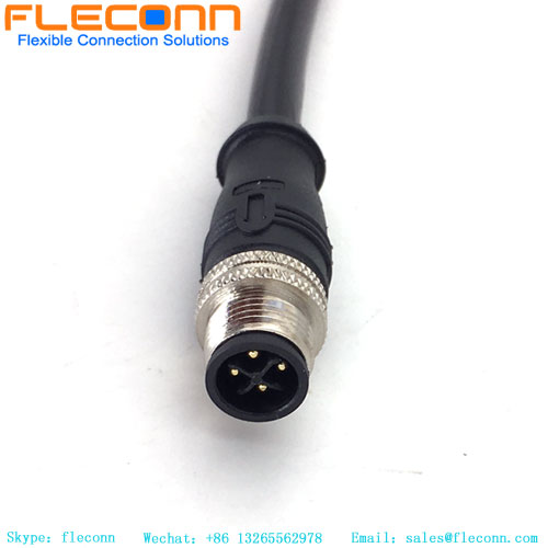
M12 plugs usually have keyway positioning, and forcibly inserting them incorrectly may damage the male and female connectors.
4、 Quick Checklist
Possible causes and solutions for the phenomenon
The sensor has no power supply. The brown/blue wire is not connected or disconnected. Check the conductivity of the power circuit
Unstable signal jumping, black and white lines not connected to the shielding layer. Add RC filtering to the signal end
Reverse the polarity of the black and white lines in the output value and switch the wiring of the black and white lines


